
Easy Reliable VOX add-on for DRA-30
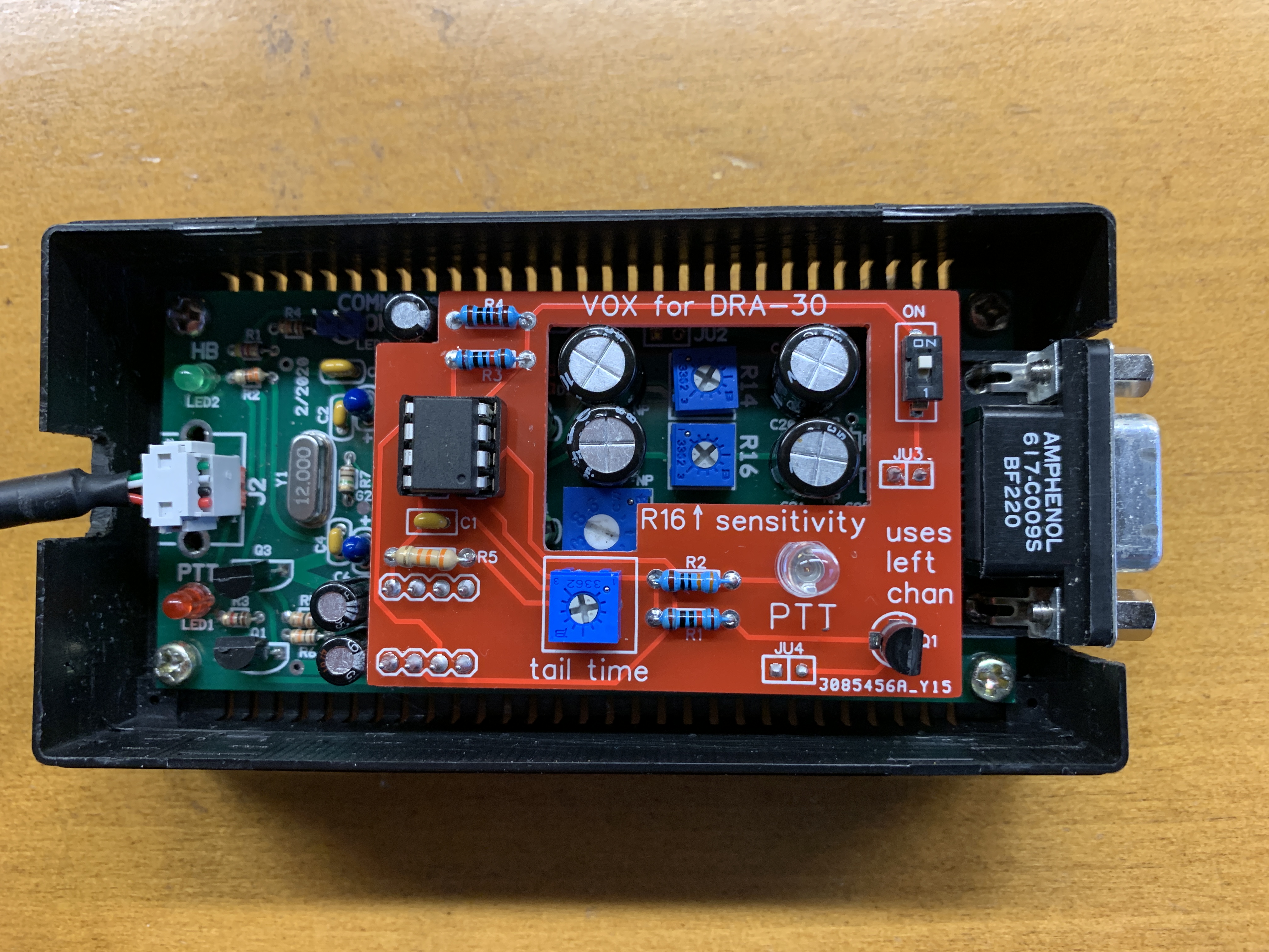
I added a VOX circuit to my Masters Communications DRA-30 USB Digital Radio Adapter Interface Board. It connects to the top of the DRA-30 and requires no modifications to it. It uses the left audio channel, leaving the right channel to go to the radio connector. It has an on/off switch, a trimpot to adjust the tail time, and uses R16 on the DRA-30 to adjust sensitivity.
This circuit adds functionality similar to Masters Communications own VOX add-on, which is not recommended for use with the DRA-30 because it needs a stronger audio signal to trigger its analog VOX circuitry. That module adds to the length of the interface by attaching to the DB-9 connector, where my module adds to its height. My circuit uses a different technique to detect the audio signal and works well with the unamplified signals from the DRA-30.
(The USB-B connector J2 on my DRA-30 has been replaced with a different connector in these photos. That modification was for a different project, has nothing to do with this project, and is not required.)
How it Attaches
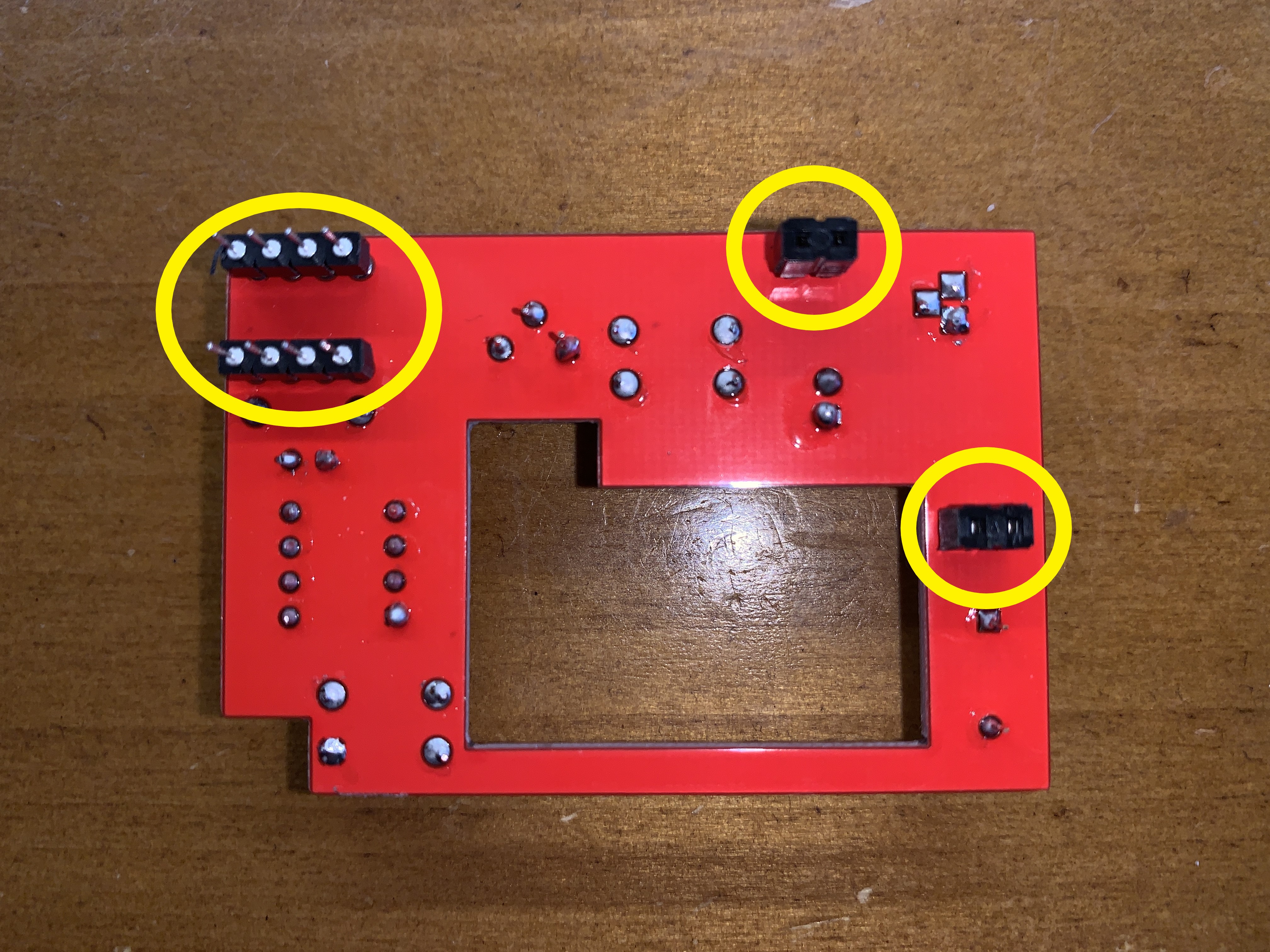
There are 8 pins on the bottom of the board that plug into the 555 timer socket on the DRA-30. It gets power and ground from there. It replaces the functionality of the 555 by listening to the heartbeat LED from the C-Media chip and sending the COMM OK signal back out to enable the C-Media GPIO PTT transistor and blue LED. It gets left audio from a socket connecting to jumper pins JU3 on the DRA-30. It gets access to the PTT line from jumper pins JU4.
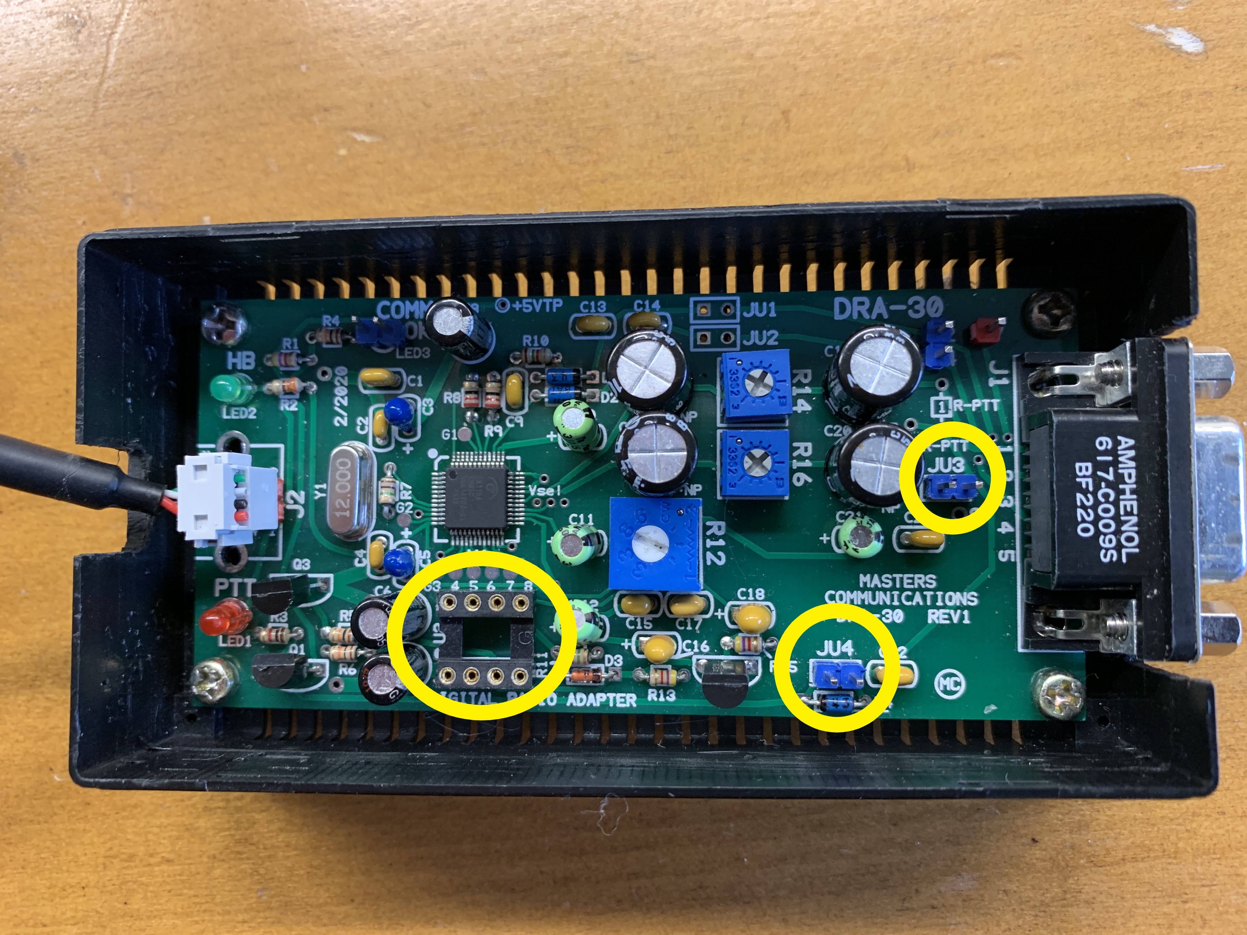
To attach, you remove the 555 timer and any jumpers from JU3 and JU4, and gently press the board into place, making sure the pins go into the sockets.
How it Works
Find the schematic here.
There is an Attiny85 microcontroller with 5 I/O pins. It takes inputs from:
- the HB signal from C-Media chip via pin 2 of the 555 timer socket
- the left audio signal from JU3
- the "tail time" trimpot value.
It outputs:
- COMM OK to pin 3 of the 555 timer socket if the HB signal is pulsing
- PTT connected to the base of a transistor connected to the radio PTT line via JU4.
The microcontroller is set to use a 1.1V reference voltage with its ADC. This is almost perfect for measuring our line-level audio signal, which is given a positive bias via a voltage divider.
If the HB is pulsing and the left audio level is above some level, the PTT pin is set high and the transistor grounds the PTT line of the radio. The sensitivity is adjustable by using R16 on the DRA-30 and/or the Windows volume control panel. The sensitivity range is good--you don't need to max out all the levels to get it to reliably trigger. You separately adjust the right channel according to the requirements of your radio.
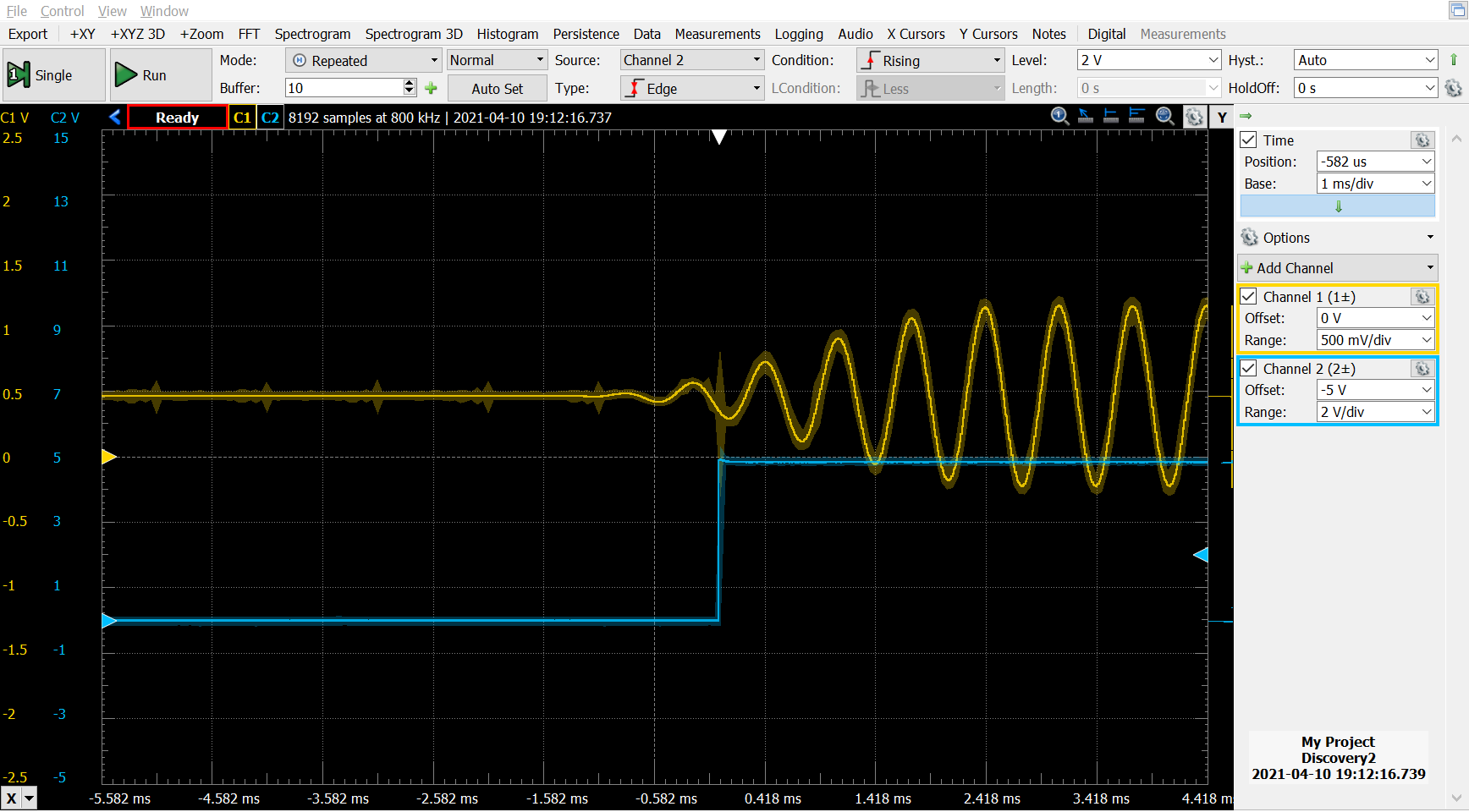
The response time varies between .5ms and 2ms from the time the audio starts (the yellow waveform in the image) to when the PTT line (the blue) is triggered. I think this is very good, but don't have a reference. It is certainly good enough.
The on/off switch simply disconnects the audio signal to disable the functionality. It can't cut power to the microcontroller because that has taken over the 555 timer's responsibility.
There is a 5 minute PTT timeout in case something goes wrong, after which PTT is released until the audio level drops out, at which time the timer is automatically reset.
You can set the tail time using the trim pot. The range is from a minimum of 40ms to a maximum of about 1 second. I normally leave this at the minimum setting. If using throb, turn the pot until the LED remains lit. This happens when the tail time is about 100ms. I don't know why you would even need anything close to 1 second.
BOM
The parts are cheap and easily available from Digi-Key. In single quantities, the total for all the electronics is $5.36. The most expensive part is the microcontroller at $1.45. Find the complete BOM here.
Assembly
It's all easy through-hole soldering. See the PCB design here. I had the boards made at JLCPCB.
I programmed the microcontroller using the Arduino IDE and a sparkfun Tiny AVR Programmer. The source code for the firmware is here.
There are two constants in the code that I determined by examining the actual audio readings when nothing is playing. These have to change with different hardware.
Power Consumption
The circuit draws 6mA when quiet, and 16mA when PTT is active and the LED is glowing.