
Teensy Radio Interface
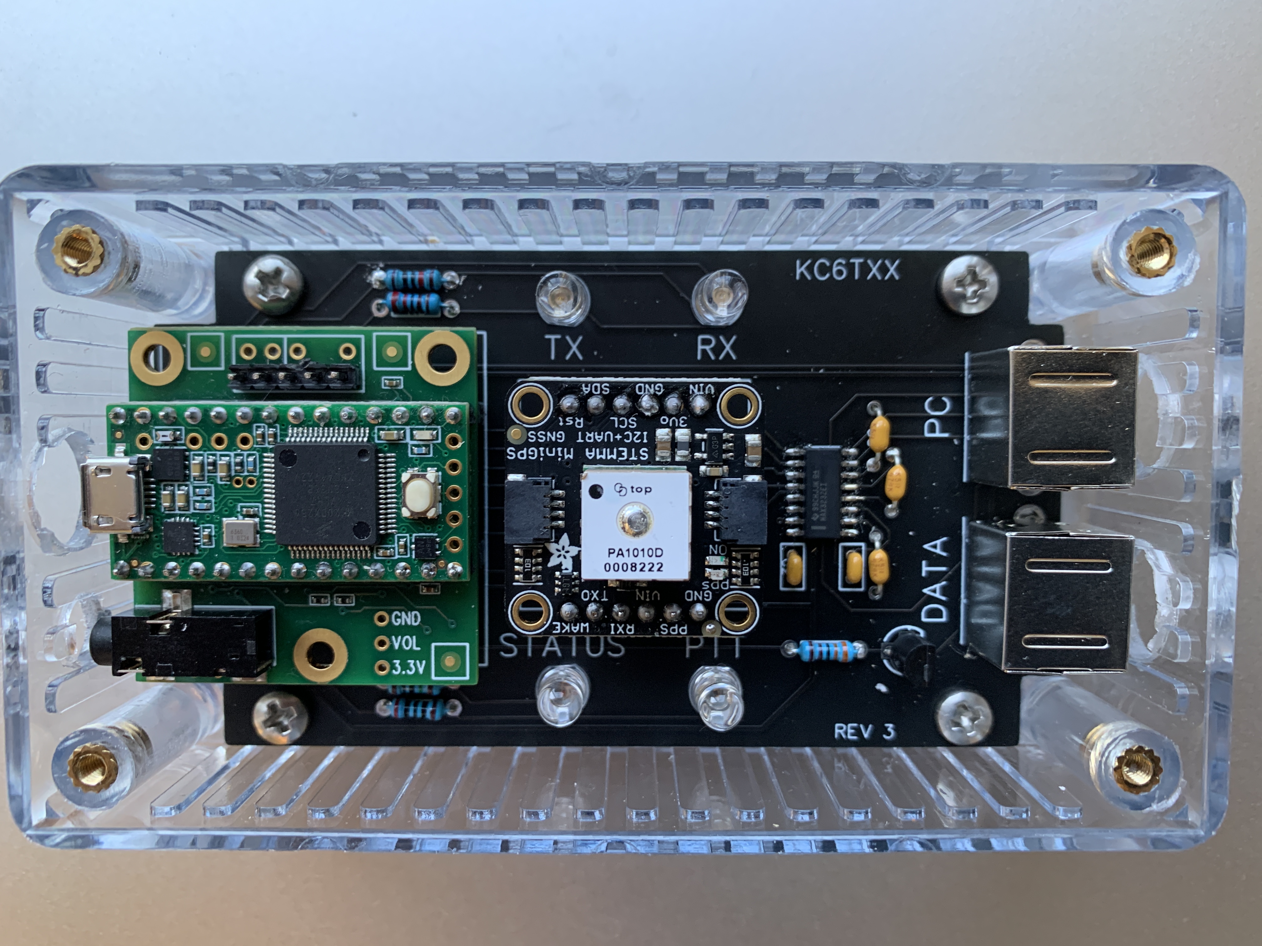
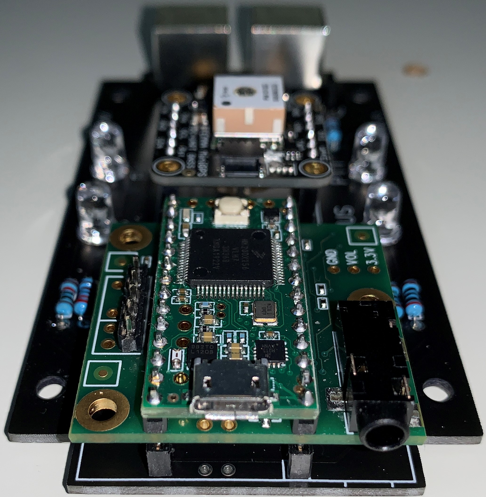
I assembled a radio interface using a Teensy 3.2 and audio board from PJRC and a custom PCB. A minimal implementation only requires those two modules plus an additional resistor and transitor for PTT and a connector for your radio. A PTT LED is also nice. I wanted some additional features: my build also has a GPS and a serial port to program and control my radio.
Overview
The interface connects to a computer with the Teensy's micro-USB connector. To the computer it presents as a USB sound card and two serial ports. The first serial port is connected to the radio and can be used for CAT control or programming the radio. The blue and green "TX" and "RX" LEDs light up whenever a byte is sent or received. This serial port can also be used for PTT via one of its control lines (RTS or DTR.) The second serial port is connected to the GPS. It can be used to receive NMEA sentences for something like APRS.
The outgoing left audio channel from the computer is connected to the radio. The outgoing right audio channel from the computer is used for VOX, if enabled. Incoming audio from radio is routed to both channels on the computer.
I found inspiration from the AnyRig interface, which is more flexible but more complicated. Because I only need it to support the one radio I own, I was able to keep it simple. For example, for my implementation, I don't need audio isolation, an opto-isolated PTT switch, or CW keying.
PTT
There are three ways to trigger PTT:
- RTS on the first serial port (see note below)
- DTR on the first serial port
- VOX.
Note: there is a known bug on Windows with RTS. I use DTR. RTS should work on Linux.
The red "PTT" LED lights when PTT is triggered.
I can configure the PTT method via either one of the serial ports. For example, to enable PTT via DTR, I send the command "ATDTRON". To disable it, I send "ATDTROFF".
There is a 5 minute PTT timeout. If PTT is held longer than that, it is released and the "STATUS" LED flashes. This is automatically reset once the PTT trigger is released.
Audio Block Diagram
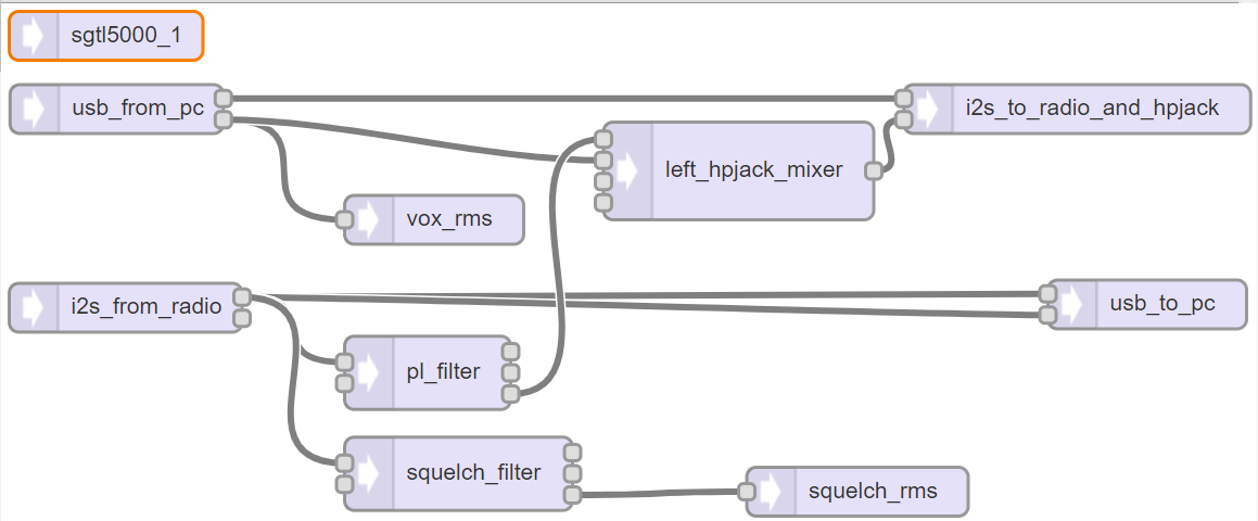
This diagram is from the Audio System Design Tool for Teensy Audio Library. See that site for details on how the library works.
Audio Levels
The audio out (to the radio) level can be adjusted via the firmware. Once I found the right level for my radio, I should never need to adjust it again. So there is no UI to change it. If I find myself needing to adjust the level, I will expose a command via the serial port interface to do it. To the computer, the output device is a "line out" device, and as such, the volume control does not adjust it. The computer volume control only controls the headphone jack volume level.
The audio in level can be controlled via the computer's input level control.
Headphone Jack
The headphone jack can be used to monitor both sides of a digital conversation, and the level can be controlled from the computer's audio control panel. Audio from the radio is routed to the right headphone channel. Audio from the computer is routed to the left headphone channel.
The headphone jack (and only the headphone jack) has a software high-pass filter on the audio from the radio to remove any PL tone hum since the audio it carries is not filtered by the radio.
The audio from the radio is also unsquelched. I implemented squelch for the headphone jack in software.
GPS
The GPS module (center of the PCB) is a PA1010D from Adafruit. It is optional and sits in a socket. That module is a PCB with some through-hole solder pads, a voltage regulator, a backup battery, two LEDS, and a CDTop CD-PA1010D module. The CDTop module contains a MediaTek MT3333. It is connected to the Teensy via one of its hardware UARTs and is seen by the computer as the second serial port. Both TX and RX are connected so that the user can send commands to the GPS via serial as well as receive data. The command reference is here.
The GPS continuously sends NMEA sentences out the second serial port at the rate of 1Hz. This can be used to set the computer's time or get position information for APRS. The tiny antenna works pretty well inside my house. I didn't change any of the GPS module's configuration parameters.
To disable the GPS, I can send a command via either serial port: "ATGPSOFF". It will remain off until I send "ATGPSON". This saves a little power. I'm using the module's "Backup Mode" where the reciever is turned off until the "wakeup" pin is set high by the microcontroller. The green LED remains on because that's powered by Adafruit's voltage regulator. But the "pulse per second" LED stops pulsing.
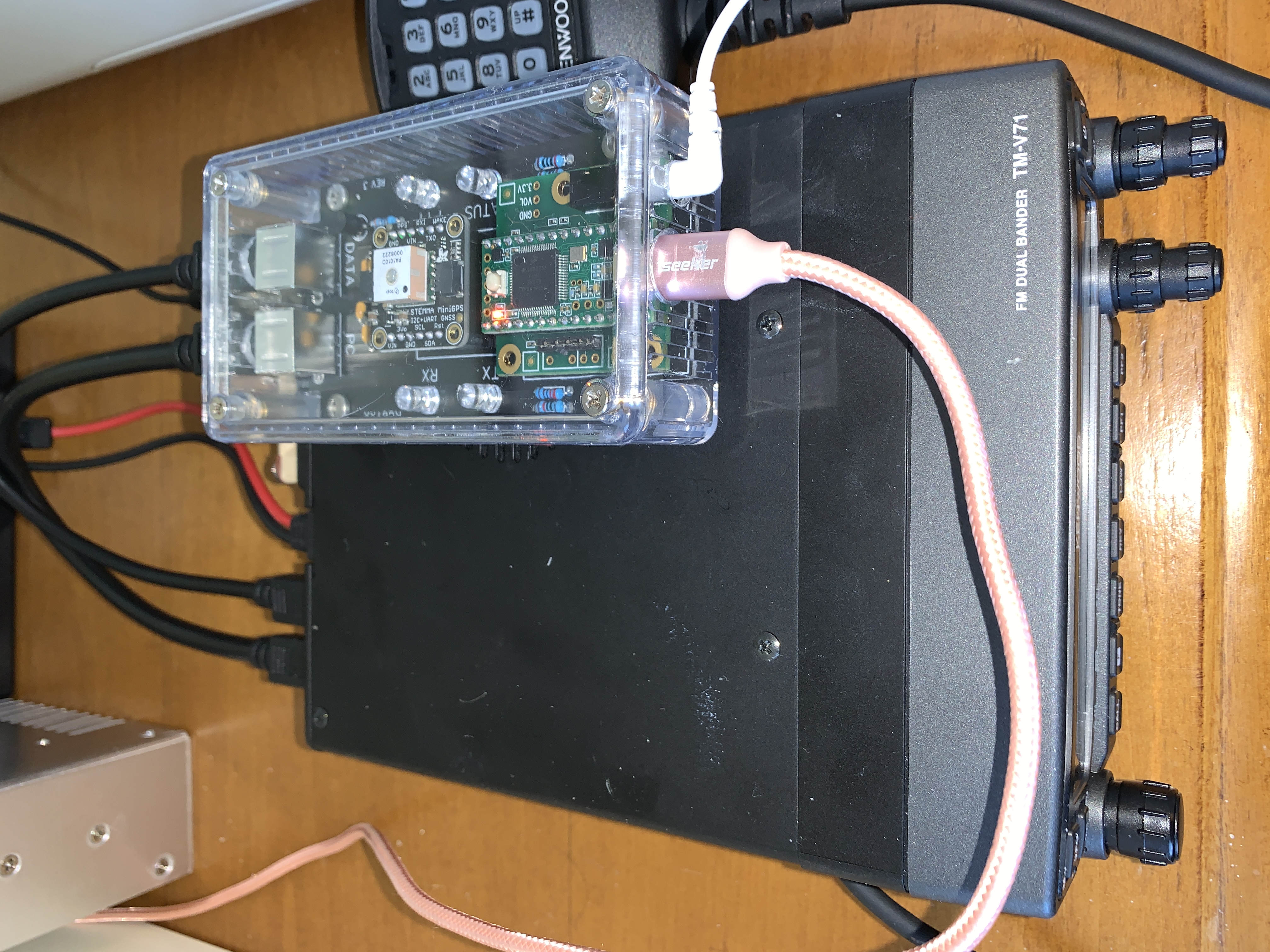
Radio Connectors
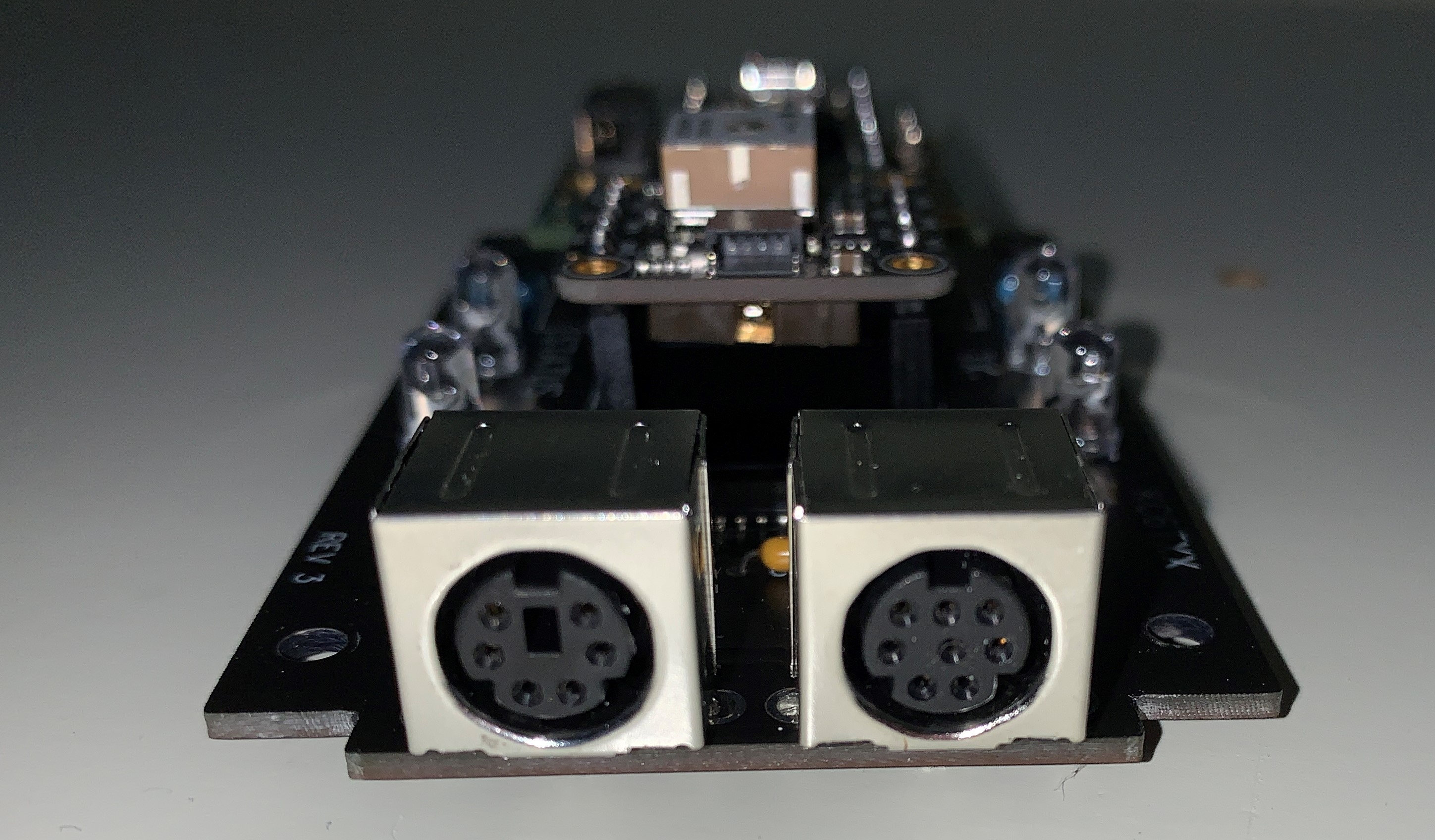
The mini-DIN connectors match those on the radio so that I can use standard cables. The labels "PC" and "DATA" on the PCB don't make much sense, but they match the labels on the radio. "DATA" (6-pin) carries audio and PTT. "PC" (8-pin) carries the serial port data. This is connected to one of the Teensy's hardware UARTs and appears to the computer as the first serial port. Note that I use a MAX3232 to get the correct RS-232 voltage levels for the radio.
Case
I am using a clear case so that I can see the LED indicators without having to mount them externally. The PTT LED is really bright, on purpose. The serial port RX and TX LEDs are much dimmer as to be less distracting. The Teensy 3.2 has a small orange LED to indicate power. The GPS module has a small green LED to indicate power, and a dim orange LED that flashes once per second when it has a positon fix.
So far I haven't had any problems due to the lack of shielding provided by a plastic case.
Measurements
Power Consumption
I run the Teensy at its slowest setting: 24MHz. With the GPS turned off, the interface draws 39mA at this rate. When it's turned on, the GPS adds between 30mA and 40mA.
Noise Floor
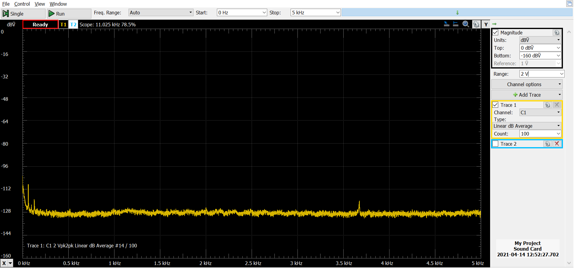
This measurement was taken with Waveforms Spectrum running with the interface selected as the input device. The radio was connected and turned off. It is an average of 100 sweeps. I'm not an expert here, but from what I've read, this is a very good result for a noise floor. I do see a small spike at 3.7kHz. I have no idea what that is, but it isn't a problem.
Audio In Frequency Response
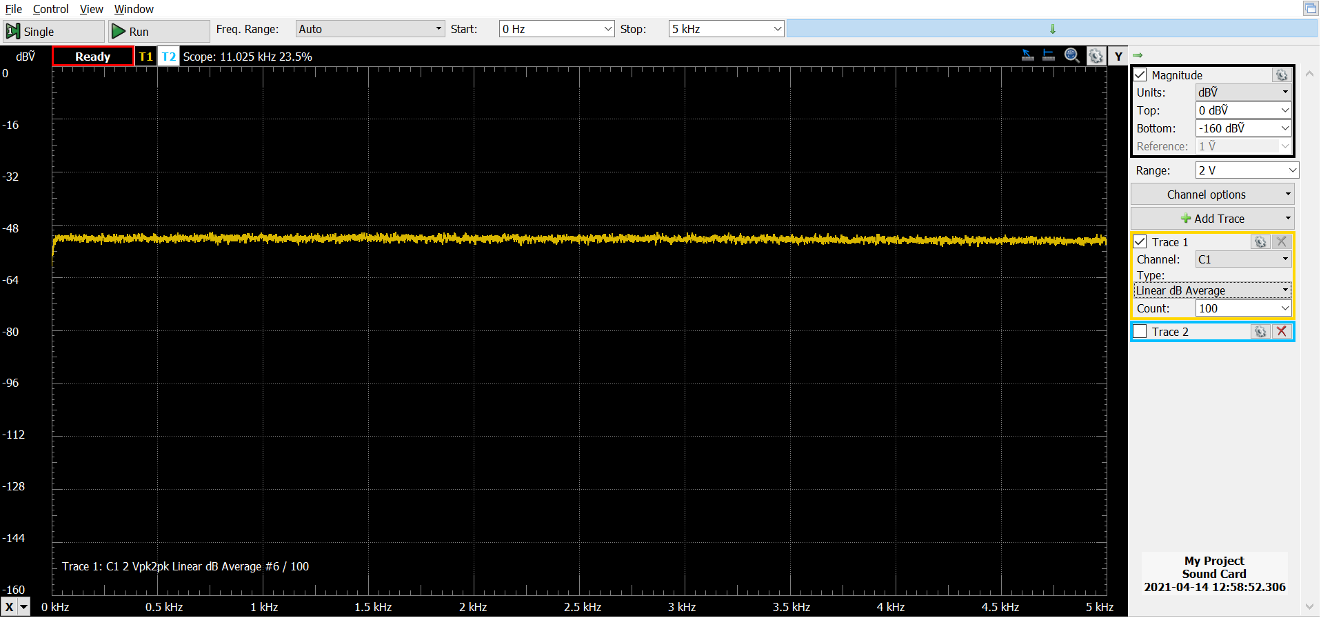
This measurement was taken with Waveforms Spectrum running with the interface selected as the input device. The radio was connected and turned on, tuned to static. The frequency response is flat. I think this is very good.
Audio Out
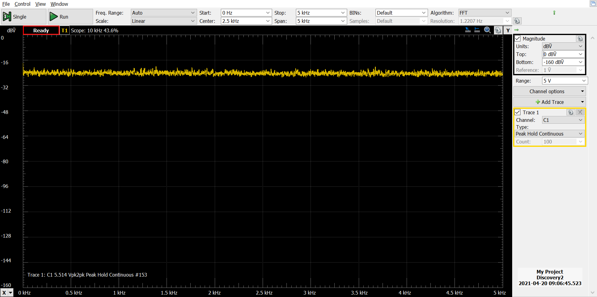
This measurement was taken with Waveforms Wavegen generating noise with the radio interface selected as the output device. The spectrum analyzer was electrically connected to the radio connector on the interface and set to record the peaks. The interface doing a good job of generating the full range of frequencies.
Fldigi
The serial port on the interface works to tune the radio: I can change the frequency in fldigi and the radio will change frequency. If I manually tune the radio, fldigi will update to reflect the new frequency. I set this up using rigcat. This is neat, but in practice I haven't found it very useful.
Here are some screenshots from fldigi's spectrum scope while receiving data over FM via a repeater. The spikes on the left are PL tones.
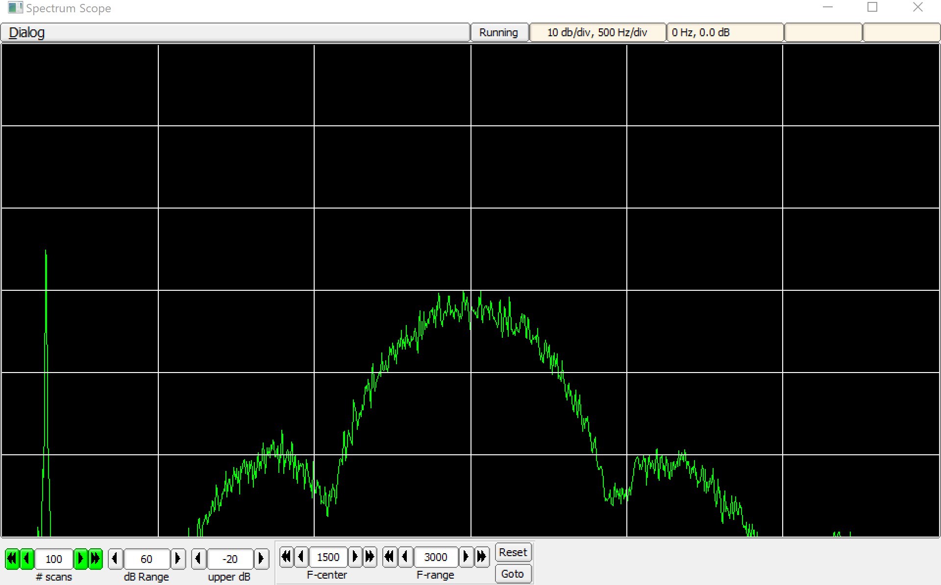 8PSK500F
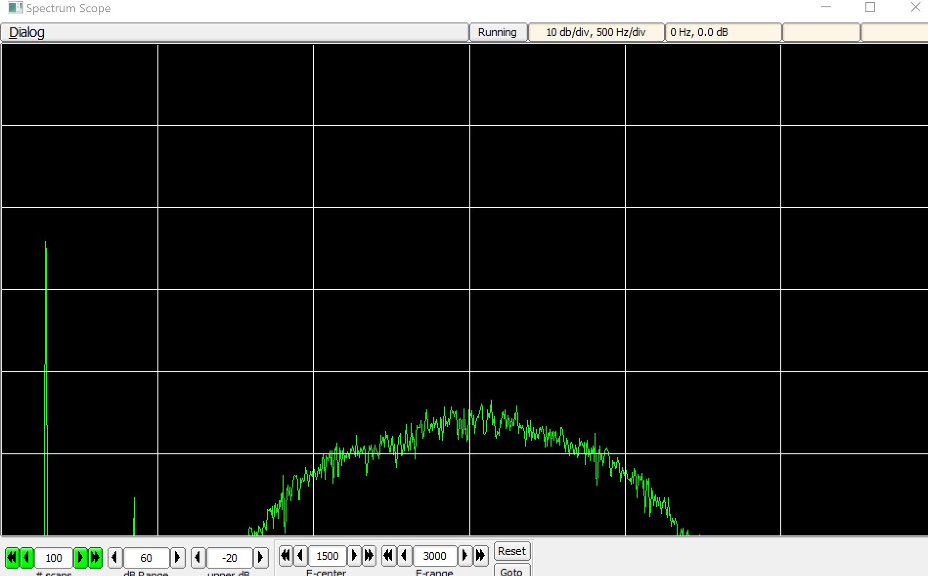 8PSK1000F
VARA FM - Problem Child
This interface doesn't work well with VARA FM--there is unexplained noise in the audio as soon as the program starts up. The docs say it requires a sound card with 48kHz support, and the Teensy is fixed at 44.1kHz. I suspect this is the problem. I don't know how to fix it.