
Radio Interface for Digital Modes
I have designed and built a radio interface add-on board for use with the Masters Communications DRA-30. My add-on board adds:
- a serial port for PTT control via RTS and/or CAT/CI-V control of the radio with TX and RX on the DB-9,
- a VOX circuit with adjustable sensitivity and tail hang time,
- a GPS,
- an integrated USB hub so only one cable is required between the computer and the interface,
- an extra USB port on the integrated hub,
- 5V on one pin of the DB-9.
The add-on board adds serial port TX and RX as TTL-level signals to the original DB-9 connector on the DRA-30. It also adds 5V to one of the lines to support converting the TTL signals to real RS-232 level signals downstream of the interface. This configuration is in no way standard and custom cables are required for every radio.
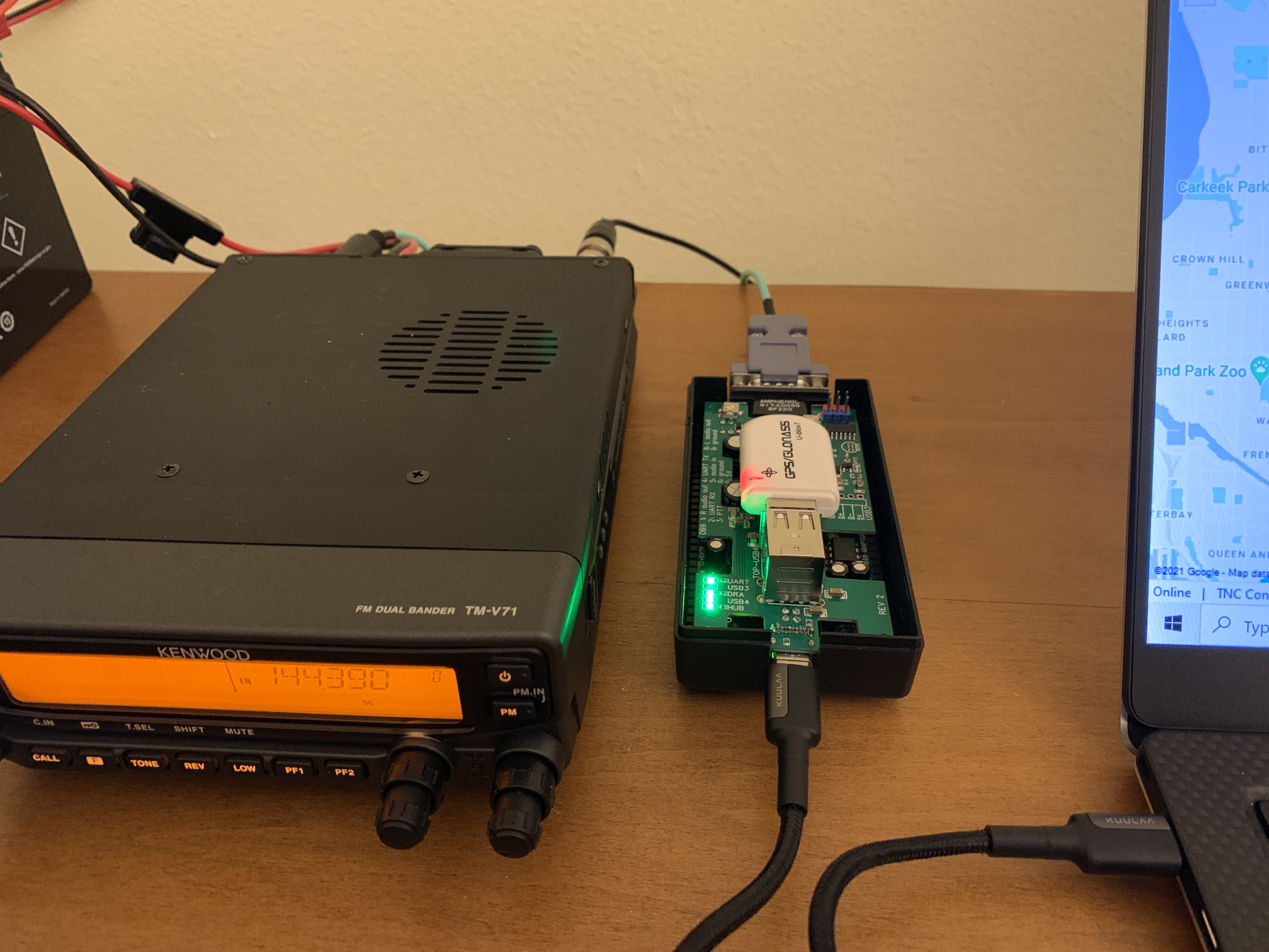
I built two cables for my radio. The teal cable carries audio in and out, PTT, and ground. It has no extra electronics, just a DB-9 on one end and a mini DIN on the other. It is fine when I don't want to talk to the radio via serial. It is the cable I use most of the time.
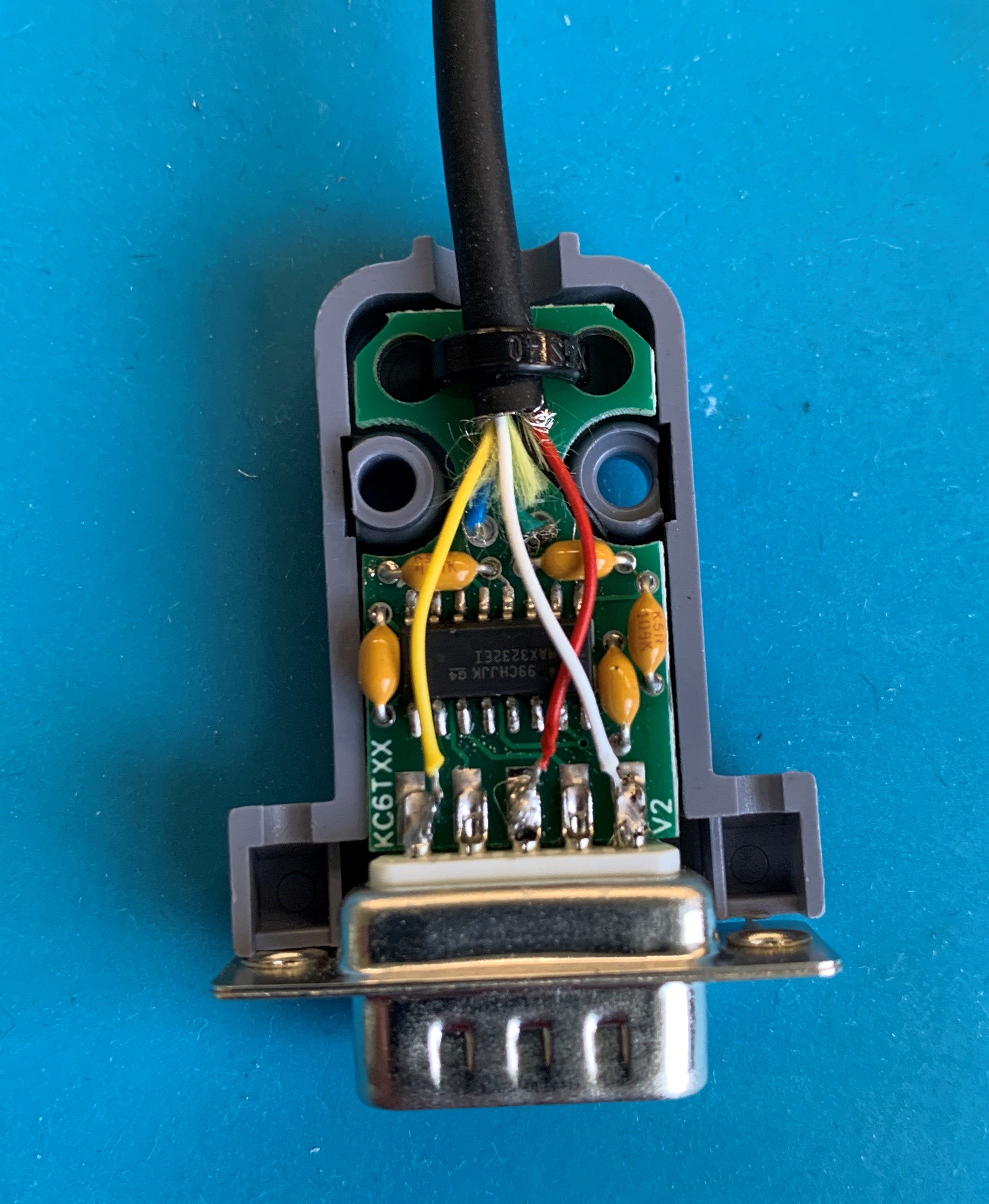
The black cable has a serial port voltage level converter inside the DB-9 shell and adds serial RX and TX lines in order to communicate with the radio.
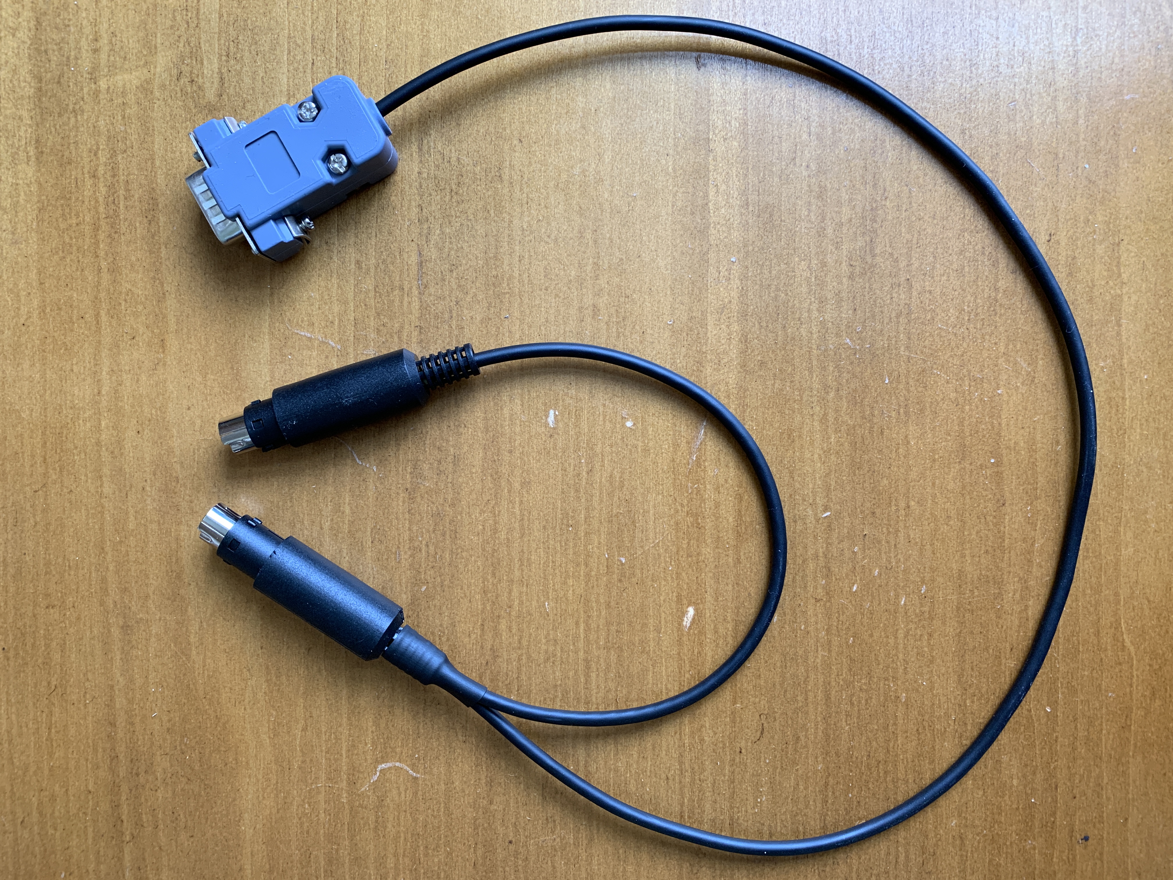
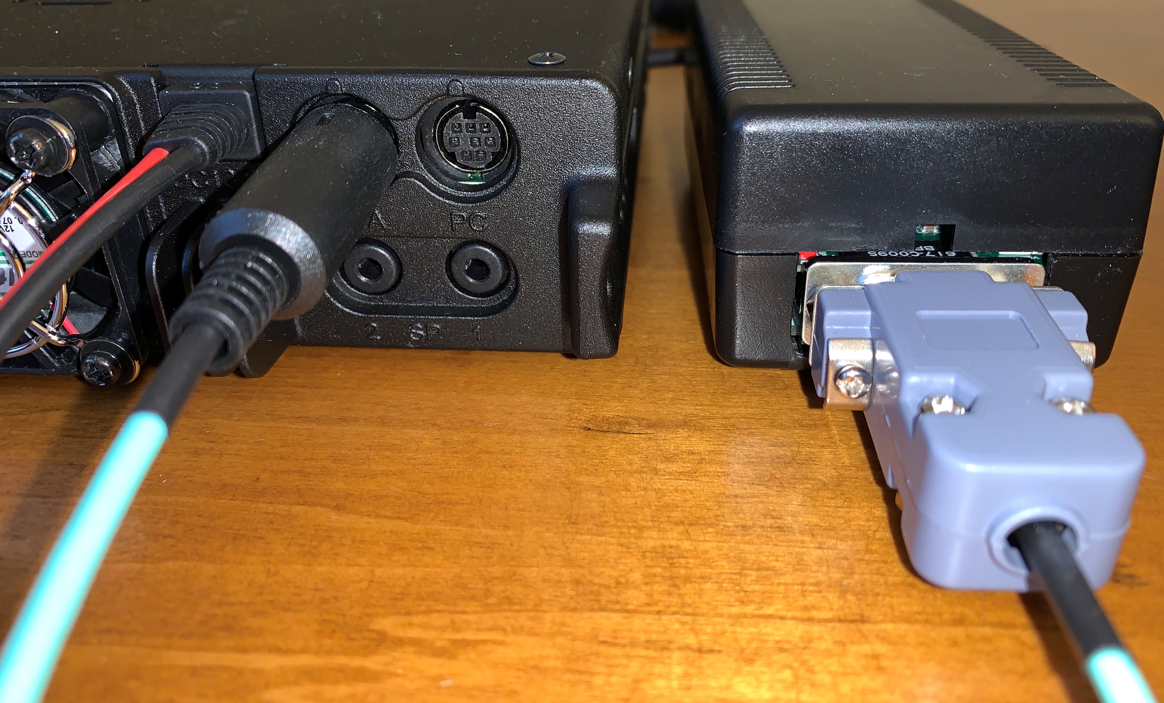
This cable has two mini DIN connectors on the radio end: one for the "PC" port, which is just for the serial lines, and one for the "DATA" port, which is for the audio and PTT lines. Fldigi can make use of the serial port, but it's not that useful on FM. But the serial port also is handy for programming the radio.
The add-on board is a circuit board that sits on top of the DRA-30, making electrical connections to it via header receptacles on the bottom that connect to header pins on the DRA-30. Some of those headers come with the DRA-30, and some I had to solder on in places where they weren't designed.
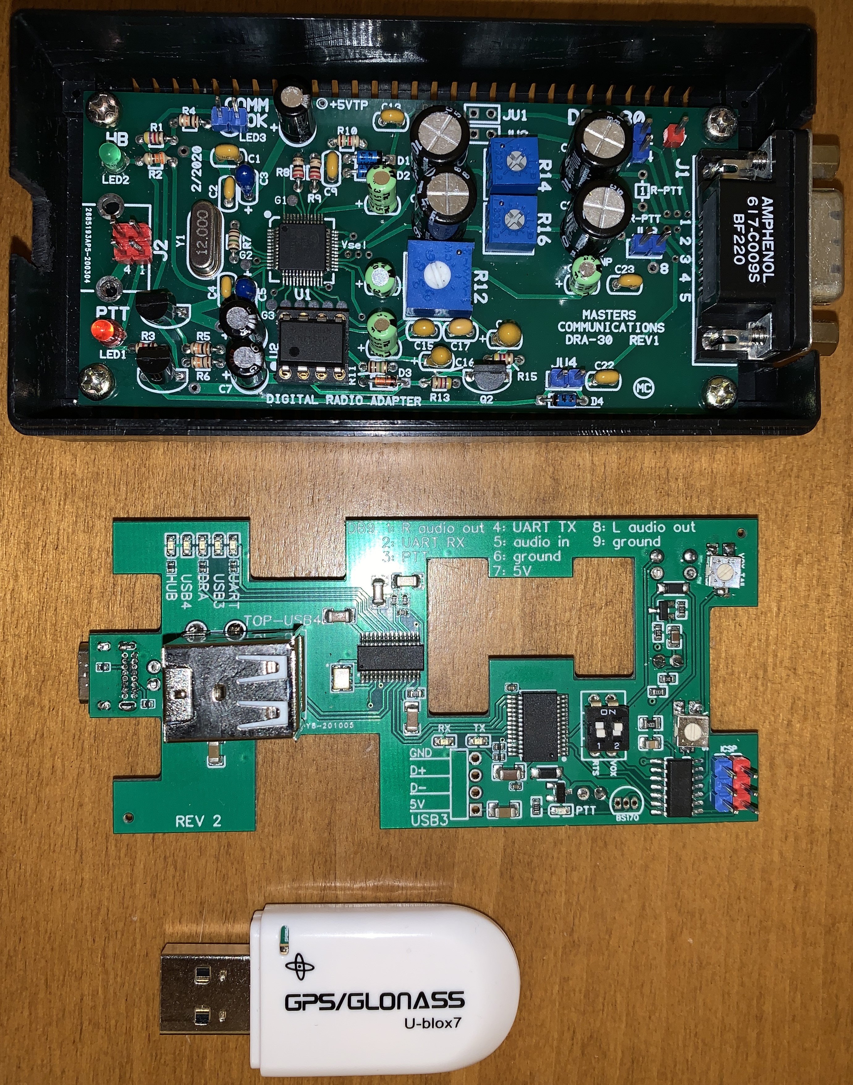
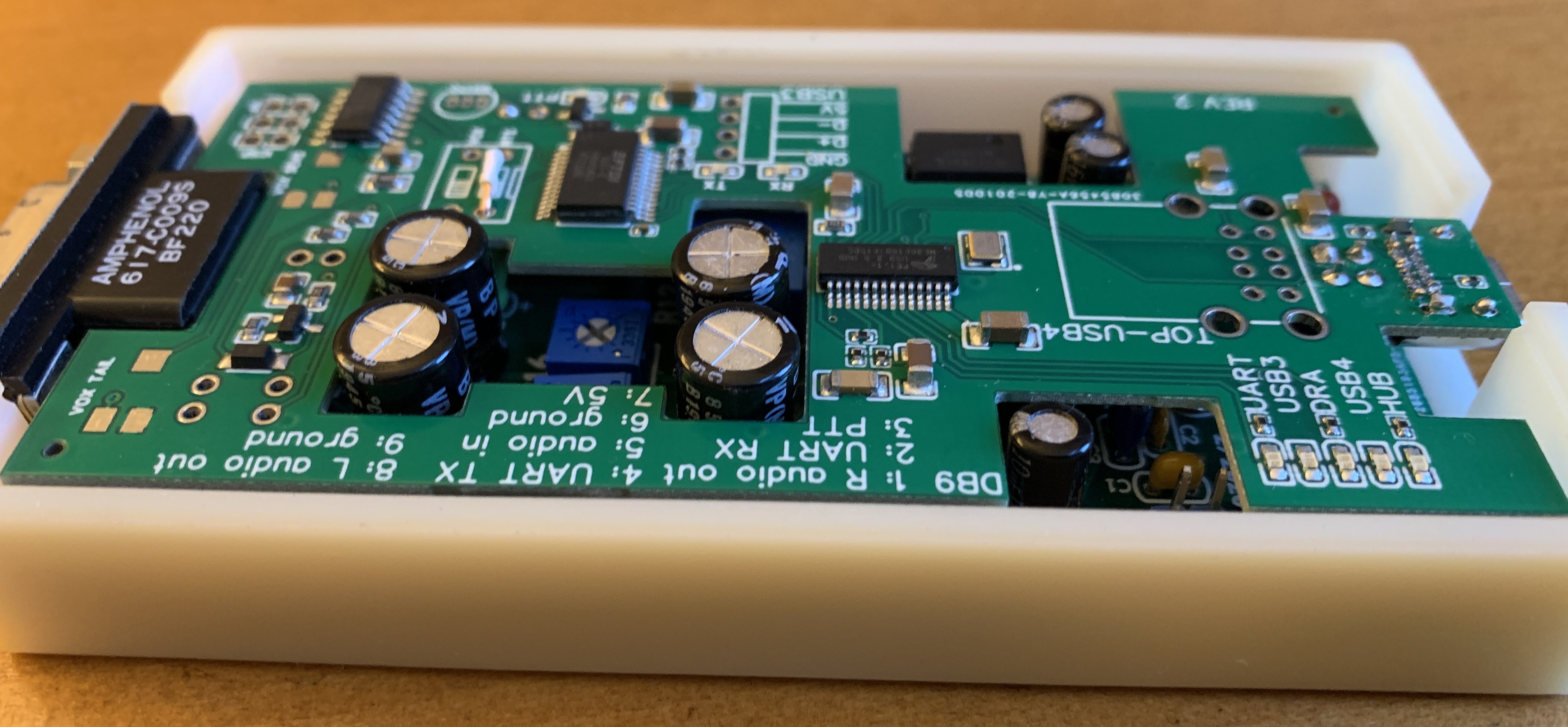
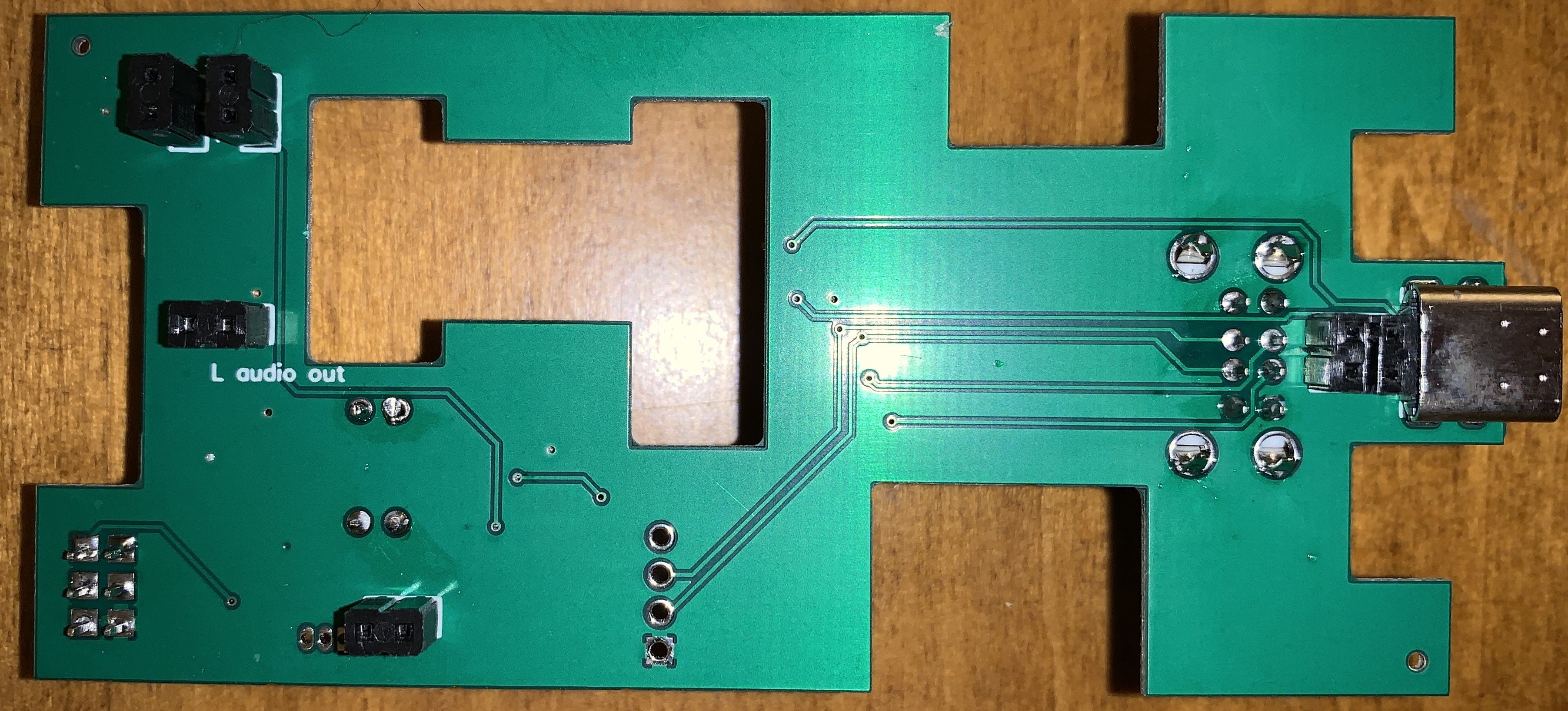
The add-on board sits very low on the DRA-30 allowing it to fit inside the original DRA-30 case (when the tall stacked USB connector for the GPS is not installed.) A USB-C connector replaces of the USB type B connector on the DRA-30. Access to the DRA-30 level adjustment trimpots and LEDs is available via cutouts in the add-on board PCB.
You can see the header pin receptacles on the bottom of the board. Notice also tha the USB-C connector is on the bottom. This allows for a better fit in the original case.
Project Motivation
The DRA-30 uses a GPIO on the Cmedia CM119A sound card chip for PTT. This works fine for Vara FM and SoundModem. But I wanted to use Fldigi and Direwolf on Windows, and neither supported this method of PTT. There is a software solution involving com0com and CAT7200 that allows a virtual com port to trigger the GPIO output on the Cmedia chip. Due to issues with how the com port driver is signed, installing this solution requires weakening the security of Windows. I'm not willing to do that. So the motivation for this project was adding a serial port so that the software could assert RTS to trigger PTT. Most software supports this scheme.
I also wanted VOX in order to use some software that doesn't support either of the methods described above. As of yet I haven't needed it, but the feature is implemented and it works really well. It certainly easier to use than the RTS method.
Simply buying a DRA-65 or DRA-70, which include VOX, would have been a perfectly fine solution for the PTT problem. Or adding a downstream VOX circuit after the DB-9, although the audio levels of the DRA-30 are too low to drive the VOX-10. But that's extra stuff hanging out the back of the interface. Plus I already had the DRA-30, and now I have not only VOX but also a USB-C connector, a GPS, and a serial port as well. Plus it was fun and educational to make.
DB-9
I have mixed feelings about the DB-9 (DE-9 for the pedantic.) On the one hand, it's an ancient and clunky connector that extends a good distance out the back of the interface. On the other hand, it is easy to wire up whatever cable configuration is needed for any radio, and there is space for the capacitor and resistor that some HTs require, or a circuit to convert the UART TTL signals to conforming RS-232 signals. A cable for each radio eliminates the need for something like the set of jumpers that the SignaLink uses to configure the lines of the radio connector.
DRA-30 Modifications
I did not install the R-PTT resistors.
I did not install JU1 and JU2 headers because I don't need COS or CTCSS and want these DB-9 lines for the serial port TX and RX instead.
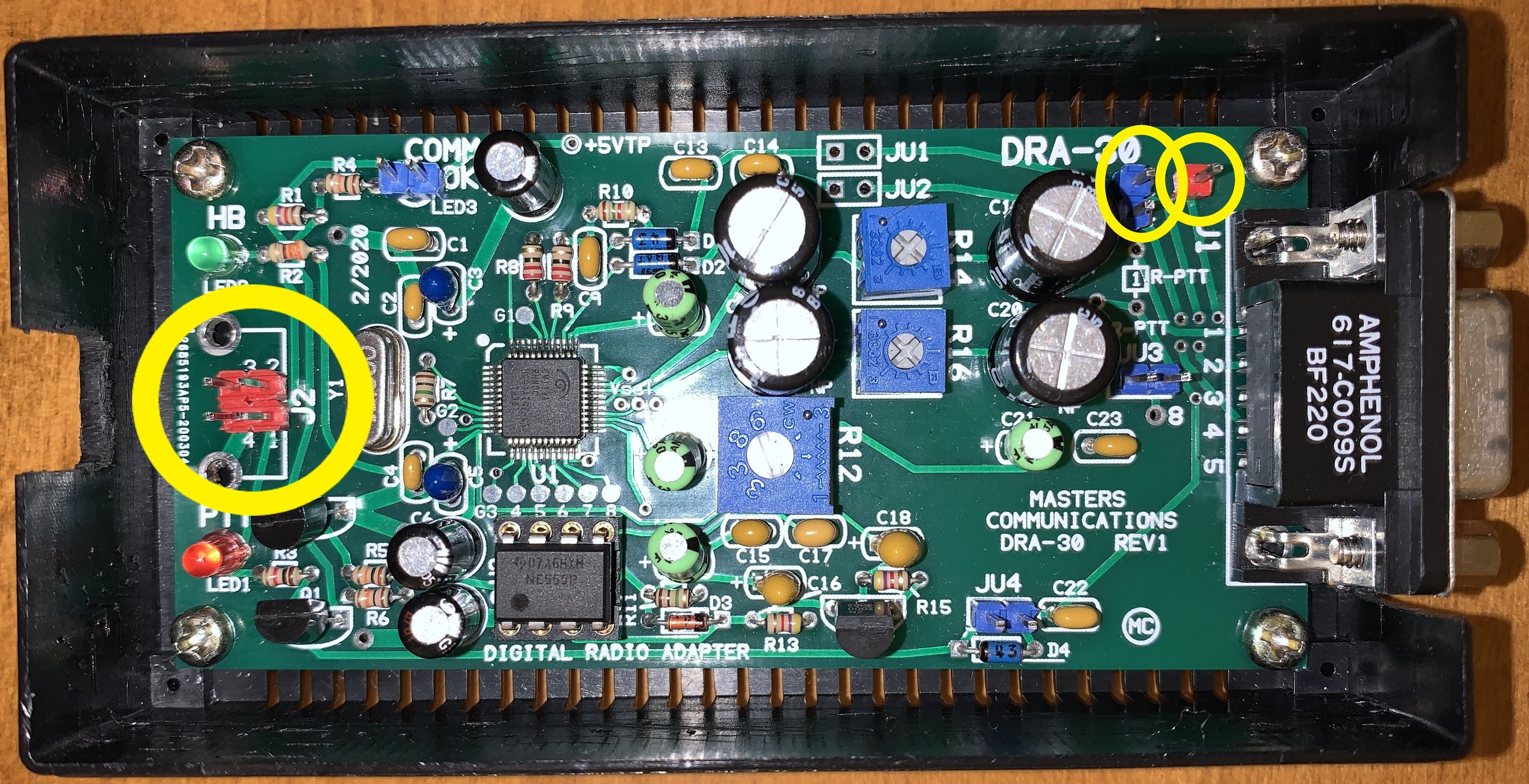
I removed the USB type B connector and replaced it with a 4-pin square header. This is so the DRA-30 can connect to the USB hub chip on the add-on board instead of directly to the computer. The pad spacing is not quite right for a standard header, but I was able to manipulate the pins enough to make it fit into the holes and the pins fit into a standard receptacle on the add-on board.
I added a 2-pin header in holes marked "2" and "4" to get access to pins 2 and 4 on the DB-9. The holes happen to be the right distance apart to accept a standard 2-pin header. I could have used the headers labeled "JU1" and "JU2" for this but chose not to because of the convenient spacing of the "2" and "4" holes. This header could be omitted if the serial port is only needed for PTT and TX and RX are not needed on the DB-9.
I added a 1-pin header to the hole marked "7" to get access to pin 7 on the DB-9. I put 5V on this pin to power a serial port level converter inside the DB-9 housing if needed. This header could be omitted if 5V is not needed.
I snipped about 1mm off the header pins to allow the board to sit lower on the DRA-30 so that it would fit inside the original case. I should have made the dimensions of the board slightly smaller so that it would fit inside the ridges on the lid of the case. This would have made snipping the header pins unnecessary, and I will make this change on the next revision of the board.
Microcontroller
There is an Attiny84 microcontroller on the board. This simplifies the PTT implementation.
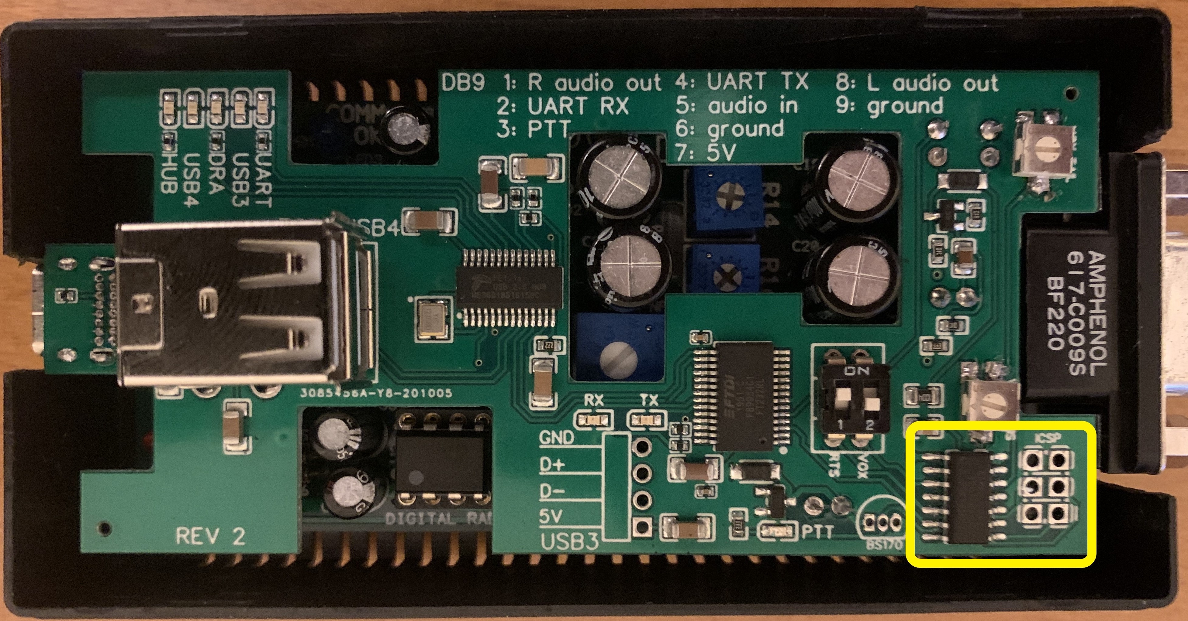
The 6 pads next to the chip are for programming it. At first I soldered on a 6-pin header, but later discovered pogo pins that I can use with just the pads.
The microcontroller listens to the following inputs:
- RTS signal from the serial port chip,
- VOX circuit audio detect level,
- RTS DIP switch position,
- VOX DIP switch position,
- VOX sensitivity trimpot setting,
- VOX tail time trimpot setting.
If the RTS DIP switch is OFF, then the serial port is ignored. Otherwise, if RTS goes low, PTT is triggered.
If the VOX DIP switch is OFF, the VOX circuitry input is ignored. Otherwise, if the audio detect signal is above the threshold specified by the VOX sensitivity pot, PTT is triggered. PTT is not released until a time specified by the tail time trimpot after the audio detect level drops off.
The microcontroller also enforces a PTT timeout to protect against RTS or VOX being stuck on.
VOX
The VOX design is inspired by this post. I have since figured out how to reduce the VOX circuit to just 2 resistors by changing the microcontrollers reference voltage to 1.1V, eliminating the need to amplify the audio signal. See this post.
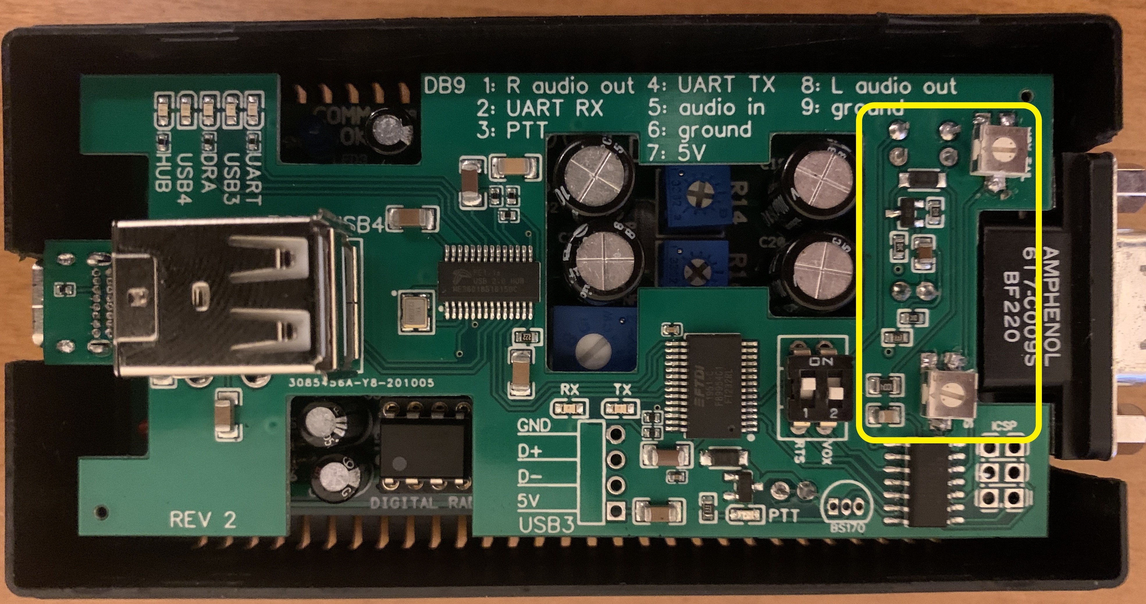
The top trimpot is to adjust the tail hang time. The bottom one is to adjust sensitivity.
The left audio channel is used as the input to the VOX circuit (via "JU3".) While both left and right audio channels are routed to the DB-9, I built my radio cables to send the right audio channel to the radios. In order for VOX to work, I configure the software to send audio to both channels: the left triggers VOX and the right goes to the radio. This allows me to adjust the left audio trimpots on DRA-30 to its highest level to increase VOX reliability while adjusting the right audio level to the appropriate level for the radio. In practice, I have both levels maxed out, and Windows audio levels at 100%.
Fldigi allows you put a constant tone on one channel to support VOX with modes that rise and fall in audio signal level that would otherwise cause the PTT to drop without a long tail hang time. For my interface, I want that tone on the left channel. In the Fldigi "Soundcard/right channel" settings, I check the following boxes:
- [x] Reverse right and left channels.
- [x] PTT tone on right audio channel.
PTT
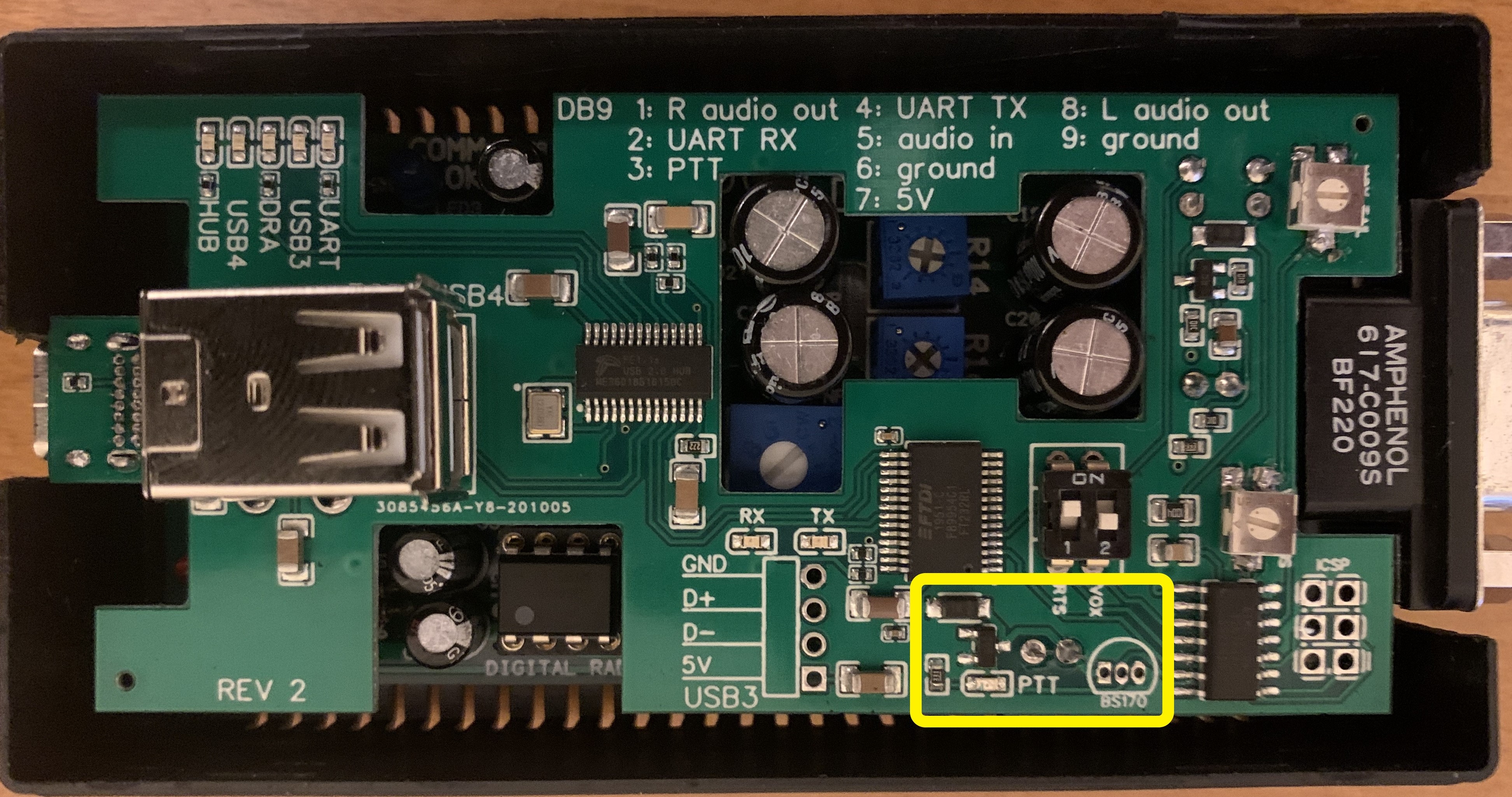
The microcontroller triggers a MOSFET to ground the PTT line on the DB-9. The SMT MOSFET can sink 300mA from the radio's PTT line to ground, which is plenty for my setup. I can also solder in a through-hole BS170 should some future radio need to sink more current, up to 500mA.
This article states that the original DRA interface design also used a MOSFET but they switched to a transistor due to RFI affecting the MOSFET's reliability. I will stick with my MOSFET for now and see what happens.
A red LED lights when PTT is triggered.
The PTT will be held for a maximum of 5 minutes each time it is triggered. I pulled this number out of the air, but if it proves to be too short I can change the microcontroller firmware. In a future revision, I would like to add an LED to indicate this timeout condition.
In my next board revision, I will add the COMM OK signal from the DRA-30 555 timer as an input to the microcontroller as a additional requirement to trigger PTT.
Serial Port
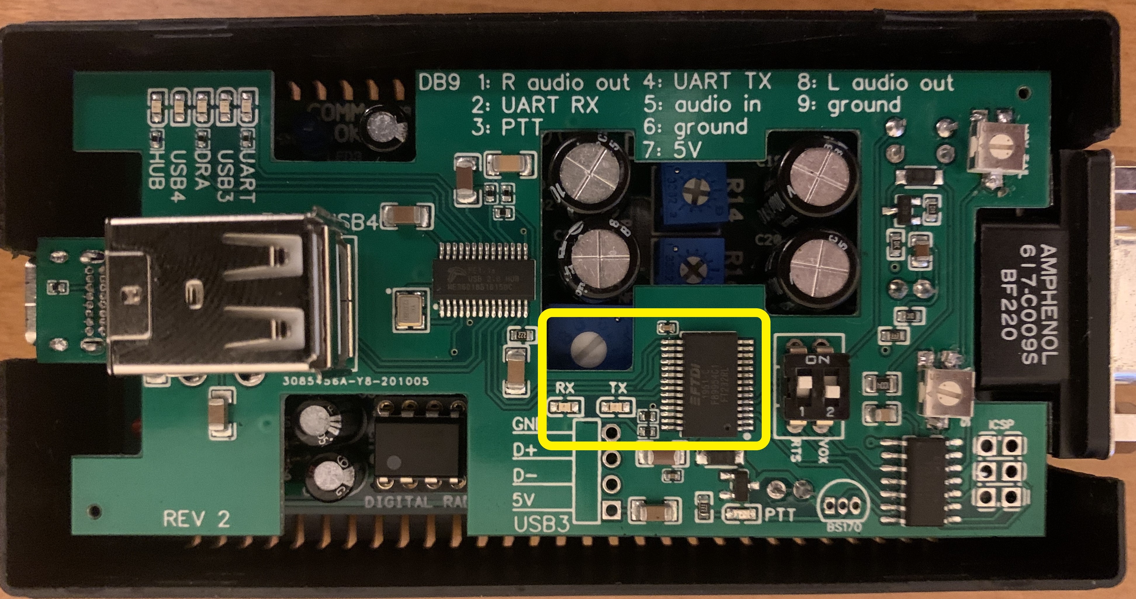
I chose the FTDI FT232R USB-to-serial port chip. I like this chip because I can configure it via a utility program if I ever need to invert the TX and RX signals. It also solves a problem with Windows asserting RTS at inopportune times.
Windows will assert RTS several times when the serial port is powered up, and when some other USB serial port is added or removed from the system. PTT will trigger and any connected and powered-on radio will transmit a few short pulses. This is painful and with similar setups you have to manage it manually by turning on the radio last or connecting it after Windows has finished doing its thing. But the FTDI chip can be configured to prevent this via the device manager: under the advanced properties settings, check "Disable Modem Ctrl At Startup" and uncheck "Serial Enumerator". This is a huge convenience.
There are TX and RX LEDs on the board that are handy for troubleshooting.
USB Hub
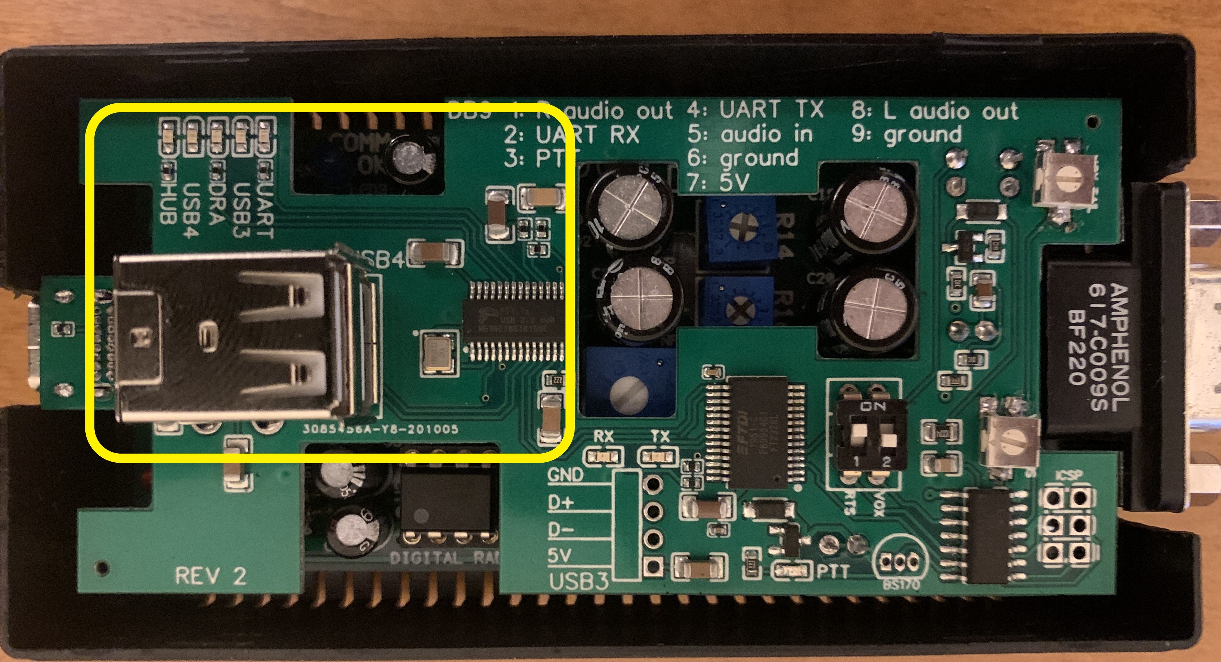
The DRA-30, the serial port, and the GPS are all USB devices. Without a hub, I would need three USB connections to the computer or an external hub. So I built the USB hub into the add-on board--it's a chip, a crystal, and a handful of capacitors and resistors. Now the hub is the only thing connected to the computer, and the serial port, DRA-30, and GPS all use ports on the hub. There is one USB port left over on the hub for future expansion. This is available via the stacked USB connector: there should be enough clearance at the bottom port to plug in a USB cable or a very flat PCB. In fact, the GPS PCB is thin enough to fit in the bottom port if removed from its white case, leaving lots of clearance for something larger to fit in the top slot. Though I'd like to keep the GPS on top so that its antenna has an unobstructed view of the sky.
There are LEDs that indicates the state of each connected device, and one for the hub itself.
GPS
Two of the USB hub ports are connected to a stacked double USB connector on the add-on board. The GPS is an unmodified dongle from U-blox that plugs into the top port of that connector. It appears to the computer as another serial port device. By default, it spits out NMEA sentences at a rate of once per second at 9600 baud. This is what I want and I didn't have to configure it in any way. This is useful for APRS, Winlink position reports, and for accurately syncing the computer's time if a network is not available.
This GPS dongle contains a battery-backed real time clock so satellite fixes are very fast.
Case
I can use the original DRA case if I don't need the GPS and stacked USB connector. Since that case is translucent, the LEDs are visible from the outside.
The taller case I found has ventilation slits in the top that allow me to see the state of the LEDs. But I have to be looking at it from a high angle to see them. I would like to mount some of the LEDs on the outside so they are easier to see. I have yet to decide if this change would be worth it.
Power Consumption
5V power comes from the USB port. The DRA-30 alone draws 30mA. With the add-on board but without the GPS, the power draw is 84mA. With the GPS attached, the total draw is 111mA. Add 10mA when the PTT LED comes on.
Final Thoughts
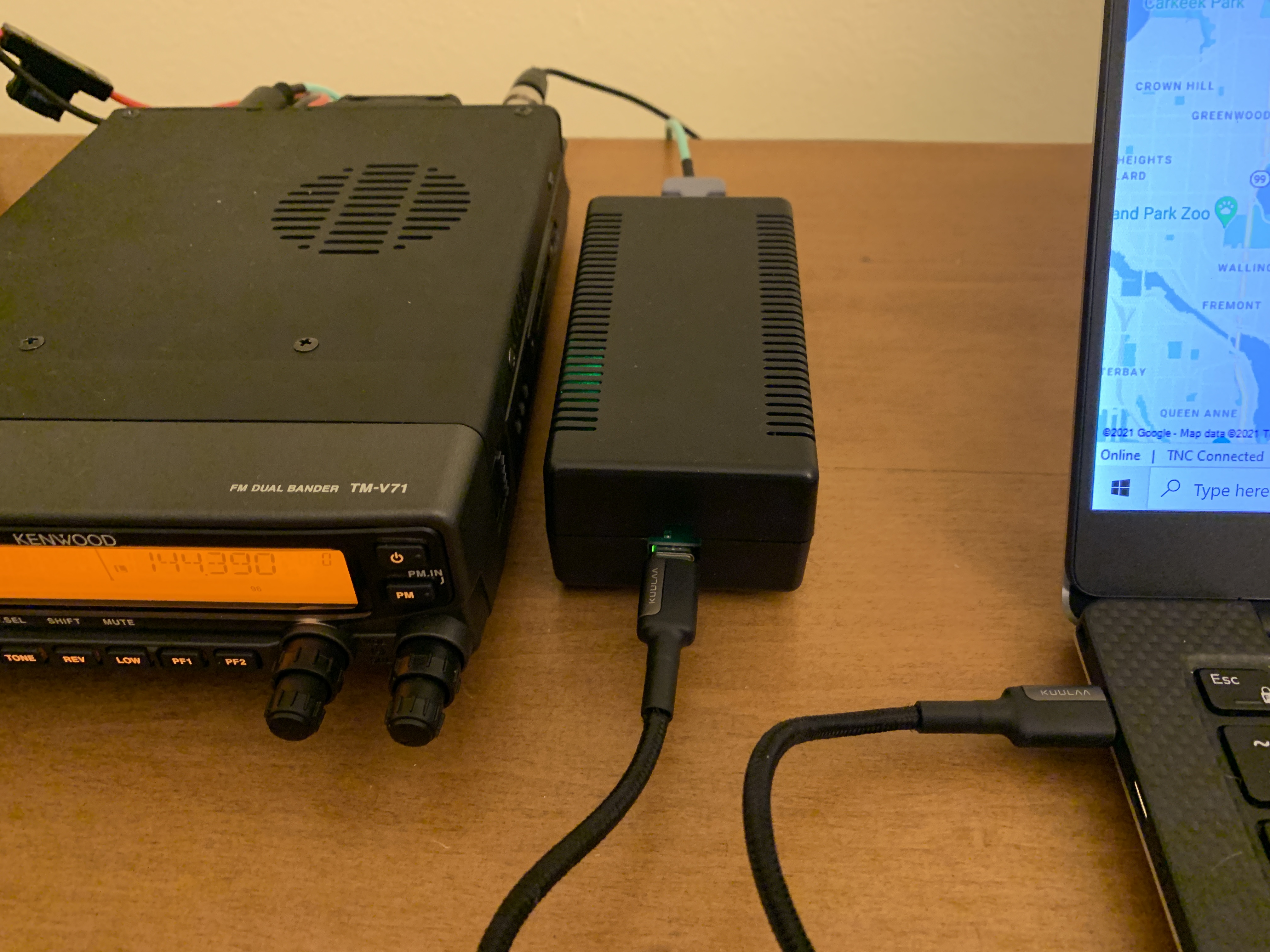
I have been using this interface and prototype versions for several months with a Yaesu FT-530 HT and a Kenwood TM-V71A dual-band mobile. I have used SoundModem, Direwolf, Vara FM, Winlink, APRS, and Fldigi. It is serving me well, but I have ideas for the next version:
- use the COMM OK signal as a prerequisite to trigger PTT,
- make the dimensions of the board slightly smaller,
- route DTR to the microcontroller as another option for PTT,
- mount the indicator LEDs on the outside of the case,
- add an LED to the microcontroller to indicate a PTT timeout condition.
If I allow the microcontroller access to the serial port TX and RX lines, I could implement a configuration interface via the serial port. Eg: AT commands. Then I could eliminate the DIP switches and/or VOX trimpots. Plus it would enable a 4th way to trigger PTT: a serial port command. Like CAT control, but to the interface instead of the radio. I don't know if this is a good idea or not.
Additionally, that would allow the interface to translate from RTS or VOX to a CAT command if such a thing were ever needed. The scenario would be a radio that only uses CAT for PTT and software that doesn't support CAT control but does support RTS. That seems unlikely, but it's an interesting capability nevertheless.
If I were to start this project over from scratch, I might start with the DRA-45 or DRA-65 in order to get the audio amplifiers. Which one depends on whether or not I think the DRA-65 VOX is good enough. If I want to be able to turn if off or configure tail hang time and level controls, I would use the DRA-45 plus my own VOX circuit. Otherwise, I would use the DRA-65.
Since I'm already building a PCB and circuit, another option is to just start with a bare Cmedia chip, duplicating the DRA's audio path circuitry. Some of the parts on the DRA boards are boilerplate to support the Cmedia chip: the crystal and bunch of capacitors. I wouldn't need the 555 and related components or the transistors because the Cmedia chip's LED and GPIO outputs would be connected to inputs on the microcontroller, which would implement the heartbeat watchdog protection in firmware.
A more powerful microcontroller and I2S audio from a Cmedia chip would simplify VOX, essentially making it a software problem. This would eliminate all the discrete components of the VOX circuit, but at the expense of a more complicated microcontroller. Maybe at that point would be better to go all in with something like this setup with a Teensy board. (Update: I made something like that.)
Maybe a microcontroller is a bad idea in an RFI environment. I guess I will find out.